qida

Product Display

Provide customers with satisfactory products

About Us

Company Profile

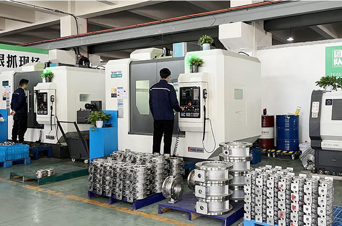
Wenzhou Qida International Trade Co., Ltd., as a professional supplier specializing in pneumatic valve accessories, is committed to providing customers with high-quality and high-performance pneumatic actuators and related accessories. The product line covers key components on various pneumatic valves, such as pneumatic actuators, limit switch boxes, solenoid valves, filters, positioners, octagonal seats, connecting shafts, etc
See More >
Profile
Workshop
Workshop
Workshop
Workshop
Workshop

News

Pay attention to the Chinese valve and keep abreast of the industry information trends
Wiring principle of limit switch box

Wiring principle of limit switch box

The wiring principle of limit switch box mainly includes two types: mechanical triggering and magnetic induction.

Mechanical trigger limit switch
Mechanical trigger limit switches open or close contacts through external force, typically consisting of an operating head, contact system, and housing. Its working principle is as follows:

Operating head: When mechanical moving parts collide with the operating head, the operating head undergoes displacement.
Contact system: Displacement is transmitted to the contact system through a transmission mechanism, causing changes in normally open or normally closed contacts.
Shell: protects the internal structure and prevents external interference.
Magnetic induction limit switch
Magnetic induction limit switches use magnetic field changes to achieve circuit control, without direct contact, with fast response speed and high accuracy. Its working principle is as follows:

Magnetic field change: When the device reaches the preset position, the magnetic field changes.
Circuit control: The switch cuts off the power supply of the motor according to changes in the magnetic field, and achieves dual protection by connecting the main contactor contacts in series.
wiring method
There are two main methods of wiring: series connection and parallel connection.

Series connection method: Connect the normally closed contacts of two travel switches in sequence and connect them to the control circuit. When the mechanical moving parts have not reached the position of the travel switch, the control circuit conducts; When the first travel switch position is reached, the control circuit is interrupted; When reaching the second travel switch position, the control circuit is completely disconnected.
Parallel connection method: Connect the normally open contacts of two travel switches to different positions in the control circuit, and control the equipment through a logic circuit. When the mechanical moving parts reach the position of any travel switch, the control circuit conducts.
Application scenarios
Automated production line: detecting the position of workpieces and controlling the production process.
Conveyor belt control: Control the forward and reverse rotation of the conveyor belt to achieve automatic back and forth operation.

2025-06-26

The basic composition of pneumatic actuators

The types and structures of adjustment mechanisms for pneumatic actuators are roughly the same, mainly due to differences in the execution mechanisms. Therefore, the introduction of pneumatic actuators is divided into two parts: the actuator and the regulating valve. Pneumatic actuators consist of two parts: the actuator and the regulating valve (regulating mechanism). According to the magnitude of the control signal, generate corresponding thrust to push the regulating valve to operate. The regulating valve is the regulating part of the pneumatic actuator. Under the action of the actuator thrust, the regulating valve produces a certain displacement or angle, directly regulating the flow rate of the fluid. 1. Pneumatic devices are mainly composed of cylinders, pistons, gear shafts, end caps, seals, screws, etc; The complete set of pneumatic equipment should also include components such as opening indication, stroke limit, solenoid valve, locator, pneumatic components, manual mechanism, signal feedback, etc. 2. The connection size between the pneumatic device and the valve should comply with the provisions of ISO5211 (bottom), GB/T12222, and GB/T12223. 3. Pneumatic devices with manual mechanisms should be able to open and close pneumatic ball valves using their manual mechanisms when the gas source is interrupted. When facing the handwheel, the handwheel or handle should rotate counterclockwise to open the valve and clockwise to close it. 4. When the end of the piston rod has internal or external threads, there should be a wrench socket suitable for standard wrenches. 5. The sealing ring of the piston should be easy to replace and maintain. 6. Pneumatic device with buffer mechanism

2025-06-26

The valve limit switch box APL310N

The valve limit switch box APL310N, as an important component in the field of industrial automation, is widely used in the signal feedback system for the opening and closing of 90 degree rotary valves such as pneumatic butterfly valves and ball valves. Its exquisite design and powerful functions provide reliable technical support for industrial process control and automation operations. This article will provide a detailed introduction to the structural characteristics, working principles, application areas, installation and maintenance of the APL310N valve limit switch box, in order to help readers better understand and apply this product.

2025-06-26

Working principle of pneumatic actuator

Core working principle The energy conversion of pneumatic actuators is based on the pressure energy of compressed air, and mechanical motion is achieved through the structure of cylinders or pneumatic motors. It is mainly divided into the following two categories: Linear motion type (straight stroke). Single acting: Compressed air pushes the piston to move in one direction, and the spring provides a restoring force. Suitable for small valves, with a simple structure but low output force. ‌‌

WhatsAppE-mailWeChat